Thiele / Small Parameters — Driver Parameter Measurement
Thiele/Small (T/S) parameters are the standard set of electro-mechanical values that describe how a loudspeaker driver behaves at low frequencies. From them you can predict a driver’s resonance, efficiency, the enclosure volume it needs, and how far the cone will move at a given power. They were formalized by Neville Thiele and Richard Small in the early 1970s and are the foundation of modern speaker-box design.
New here? The Cone Excursion and Infra-Bass SPL plots each have a “Load Example ▸” button that drops in a worked driver, so you can explore the curves and the draggable cursor before measuring your own.
Use this tool to:
- Measure a driver’s full T/S parameter set without a calibrated test box
- Predict the enclosure volume a driver needs, and which alignment (sealed or vented) suits it
- Check predicted cone excursion against Xmax at a given drive voltage
- Estimate infra-bass max SPL and volume displacement
- Compare drivers and size subwoofer arrays
The Parameters
- Fs — Free-air resonance (Hz): the frequency at which the cone moves most freely.
- Re — Voice-coil DC resistance (Ω).
- Qms, Qes, Qts — Mechanical, electrical and total Q at resonance. Qts (≈0.2–0.6 for woofers) drives the alignment: low Qts favours vented boxes, higher Qts suits sealed.
- Vas — Equivalent compliance volume (litres): the volume of air with the same springiness as the suspension. Bigger Vas = softer suspension = larger box.
- Mms — Moving mass (g): cone + voice coil + the air load on the cone.
- Cms — Suspension compliance (µm/N): how easily the cone is pushed.
- Rms — Mechanical resistance (N·s/m): suspension damping/losses.
- Bl — Motor strength (T·m): the magnetic force factor of magnet × voice coil.
- Sd — Effective cone area (cm²), derived from the effective diameter.
- Xmax — Rated peak linear excursion (mm): how far the cone can travel cleanly each way.
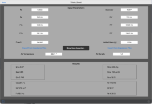
How This Tool Works — the Added-Mass Method
This module derives the full parameter set from two impedance measurements using the industry-standard added-mass technique — no calibrated test box required.
- Free-air sweep. Measure the driver’s impedance in free air with the AudioTools Impedance module, then tap “Import from Impedance Files” on the left to pull in Re, Fs, F1, F2 and Zmax — or type them by hand.
- Diameter. Enter the driver’s effective cone diameter (inches or cm, following your app’s distance units). This sets Sd.
- Add a known mass. Fix a known weight (e.g. 10–20 g of museum putty) onto the cone and run a second impedance sweep. The resonance drops to a lower value, Fs′.
- Mass-loaded values. Import (or type) Fs′ on the right, and enter the Added Mass in grams.
- Read the results. The tool computes Qms/Qes/Qts, Vas, Mms, Cms, Rms, Bl and Sd. Use the file button to Save or Recall complete measurements.
Cone Excursion
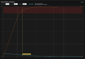
Tap “Show Cone Excursion ▸”, enter the driver’s rated Xmax and a drive voltage, and the tool plots predicted peak cone displacement |X(f)| versus frequency (cyan, left mm axis). The red line marks Xmax and the shaded band is the over-excursion danger zone — where the driver distorts or bottoms out. The readout gives the voltage (and power into Re) at which the cone reaches Xmax. Tap “Load Example” to see a worked driver.
Infra-Bass SPL & Volume Displacement
The orange curve (right dB axis) is the Reference Max SPL @1 m — how loud the driver can play at each frequency when the cone is driven to Xmax. It is computed from the cone area and excursion using the Eargle baffled-piston relation:
Lp = 20 · log10[ Xpeak · f² · a² / 1180 ]
where Xpeak is the peak excursion (mm), a = √(Sd/π) is the effective piston radius (mm), and f is in Hz. Because output is displacement-limited down low, this curve rises about +12 dB per octave through the infra-bass region (≈10–80 Hz).
Volume Displacement (VD = Sd · Xmax) is the headline infra-bass capability number — the swept air volume. Nameplate Xmax is ambiguous (manufacturers quote mechanical, distortion-, compliance- or force-factor-limited values), so treat VD as an estimate; a measured value from a CTA-2010 max-SPL test is more meaningful.
Controls
- Half-space (2π) is the default — a sub on the floor against a wall. Full-space (free-air, 4π) is 6 dB lower.
- Drivers: scales for N identical units (+20·log10 N to SPL, ×N to VD).
- Power (W): the rated power caps the SPL where the driver becomes power-limited. In the deep bass the cone is excursion-limited (reaches Xmax); higher up it can’t reach Xmax at rated power, so the curve flattens at the driver’s true max SPL rather than the theoretical +12 dB/oct ceiling. Leave it blank to see the excursion-limited ceiling only.
- Cursor: drag the cursor for the frequency / excursion / SPL readout at any point.
What This Number Is (and Isn’t)
It is an anechoic, far-field reference SPL at 1 m, not the absolute level you will hear in a room. Predictions are only meaningful below the lowest room mode (wavelength longer than the room’s largest dimension, e.g. < ~43 Hz for an 8 m room); in that region a real small room adds substantial room gain on top of this figure, while wall/ceiling losses (drywall) subtract from it. Use the curve for comparing drivers and sizing arrays, not as a guaranteed in-room SPL.
Tips
- Measure in a quiet, draught-free spot and hold the driver firmly.
- The added mass should drop Fs noticeably — roughly 10–30%.
- Effective diameter is taken to about the middle of the surround, not the outer frame.
- Air temperature and density slightly affect Vas; set them for best accuracy.
T/S accuracy depends on clean free-air and mass-loaded impedance sweeps and a clear Fs shift from the added mass. The infra-bass SPL and excursion curves are anechoic 1 m references for comparing drivers and sizing arrays — not guaranteed in-room levels.